Airborne VLF System - GSM-90AV
Supplied By: GEM Systems, Canada
Rs. 0.00
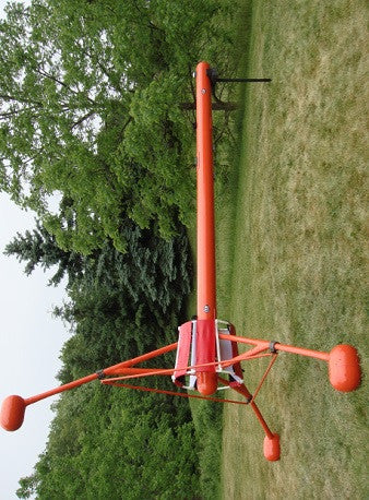
GSM-90AV: Airborne VLF System
Technically Superior
This GSM-90AV VLF System provides true measurements of the Vertical in-phase & Out-ofphase components as % of total field within the VLF frequency range of 15 - 30kHz. Many older systems only measure the total field and quadrature components of the field. The airborne system features two 3-coil sensors that acquire data from 2 VLF transmitting stations simultaneously without sensor orientation. Data include in-phase, out-of-phase, horizontal components in x and y and field strength in picoTesla (pT).
The GSM - 90AV also has a correction for the tilt level of the VLF sensor for up to 10° from the horizontal plane.

About - VLF
The VLF-EM (Very Low Frequency Electromagnetics) survey method is a passive electromagnetic system that utilizes distant, globally positioned, transmitters broadcasting at frequencies in the range of 15kHz and 30kHz. (in some cases a private/custom transmitter may be utilised in regions with sparse transmitters) In a VLF investigation, the magnetic field components of the transmitted signal, which are effected by local ground conditions, are measured.
GSM-90AV VLF Applications:
-
Resistivity imaging and bedrock mapping
-
Delineate contrasts in conductivity at depth
-
Map geological contacts, faults
-
Search for mineralized bodies
-
Water exploration
GEM/EMTOMO - VLF Resistivity
GEM uses the VLF2DMF Software platform created by EMTOMO TM. This program provides 2D inversion of multi-frequency VLF-EM data.

The package includes a map module for display of the survey, the selection of profiles for inversion and displays the survey results. The program can also be used for modeling studies. The user can build a complex resistivity model and calculate its VLF-EM response. Features include;
-
2d resistivity sections
-
Resistivity depth plan slices
-
Forward Modeling
-
Fraser Filter
-
Karous-Hjelt Filter (current density sections)
The inversion procedure used in VLF2DMF is two-dimensional (2-D) and is based on the Occam technique (e.g. DeGroot and Constable 1990, Sasaki 1989, Sasaki 2001).The forward modelling of VLF2DMF program is based on the finite-element method.
Why Use VLF
VLF surveying has been utilised since 1964 as a rapid means to find large linear conductive features to provide information about the subsurface for geological mapping. Large area surveys have provided regional structural information but due to a lack of quantitative information such as depth to structure information the method had been marginalised until quite recently. In 2007, the Geological Survey of Sweden demonstrated that not only could VLF data be rapidly and efficiently collected it could provide excellent structure and resistivity information to depths of 100 m and theoretically to over 200 m.
Advances in both technology to collect VLF data properly and advances in computer technology and mathematical inversion techniques have provided the industry with a new cost-effective means for imaging the top 100 metres of the earth.
The robust GEM multi frequency GSM 90AV VLF system, provides the user with a practical way to collect meaningful resistivity information in a very cost effective manner. In addition, the VLF system can be easily combined with GEM magnetometers for additional subsurface insight.
VLF Applications
A Very Low Frequency (VLF) investigation is well suited to the location of geological faults (and approximating their altitudes), some types of geologic contacts, and buried conductive bodies including water-bearing faults. The VLF-EM Frequency method is a passive system as it utilizes a fixed position transmitter broadcasting a frequency between 15 and 30Kz.
In a VLF investigation, the magnetic field components of the transmitted signal are measured.
This method can delineate contrasts in conductivity at depth and is used in the search for contacts, faults, mineralized bodies, overburden, fractures, voids and for a variety of other purposes, including the location of utility lines and sighting of water wells.
Targets are of two primary type:
-
Linear trends of considerable length that are more than 30° from the horizontal
-
Broader zones of lateral changes in conductivity related to such features as plumes or alteration zones

Specifications
| VLF Parameter | Specifications |
|---|---|
| VLF Frequency: | 2 simultaneous stations between 15 & 30.0 kHz |
| Parameters: | Vertical in-phase and out-of-phase components as % of total field 2 components of horizontal field amplitude Total field strength in pT |
| Resolution: | 0.1% of total field for VLF fields of 5 pT or stronger |
| Tilt Correction: | Horizontal: ± 10° |
| Digital Compass: | Heading, pitch and roll at 10Hz |
| Operating Temperature: | -20°C to +50°C |
| Dimensions: | Sensor :14 x 15 x 11 cm. (5.5 x 6 x 5 inches) Console: 22.3 x 6.9cm x 2.4 cm |
| Weights: | Sensor: 1.0 kg Console: 2.1 kg Towed Bird: 2.1 kg |
| Power Source: | External 22-32V, 18 Ah @24V 12V for VLF Console |
| Storage: | Automatic with: time, coordinates, slope, EM field, frequency, in- and out-of-phase vertical, and both horizontal components for each selected station |
| Sampling and Data Output: | 10, 5, 2, 1 Hz with RS-232 output Data export in standard XYZ (i.e. line-oriented) Format for easy use in standard commercial software programs |
*The GSM 90AV VLF system comes complete with an industry leading three year warranty with VLF2DMF software by EMTOMO optional

Related Products